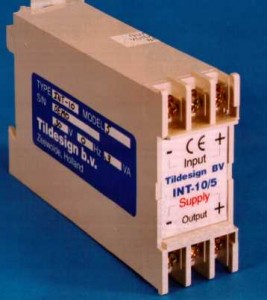
 The INT-10 is a hydraulic control component (signal converter) that converts standardized and commopnly used industrial control signals into the required control signal for Sauer-Danfoss PVG-32 and PVG-120 proportional hydraulic valves. The appropriate control signal to drive a Sauer-Danfoss valve is a percentage of the supply voltage. This way the valve can be controlled by aan analog joystick (potentiometer). The output signal of a joystick is a percentage of the supply voltage, 50% when it is in it’s base position and 25% or 75% at the limits of the joystick.
PLC’s usually are not capable of giving such an output. The output signal from a PLC is a standardized industrial control signal (0-10 V, -10..+10 V, 0-20 mA, 4-20 mA). To solve this differencem we developed the INT-10 hydraulic signal converter which converts a common control signal into a percentage of the supply voltage. That way a Danfoss PVG-32 proportional hydraulic valve can be controlled easily by a PLC and in the appropriate way.
In other words, the INT-10 solves your interface problem between PLC and Danfoss valve in a very proper and easy way.
The INT-10 has a galvanic isolation built in. That means the input and the output are electrically isolated from each other. The advantages are that interference on the power supply can’t reach the PLC. And it is also allowed to reverse the input signal. A PLC with an output of 0-10 V can still drive an INT-10/5 that requires -10 .. +10 V as an input signal. So a galvanic isolation protects your precious electronics and provides ease of use.
Available models to drive PVG-32 valves
The INT-10 can be delivered in 7 different models, depending on the input signal.
Please note that the unit which is the safest to use is INT-10/5. This is explained under safety issues driving Sauer-Danfoss PVG-32 valves.
We usually keep enough stock to deliver immediately. If the quantities shown below are less than you need, just give us a call or send us an e-mail. We can usually manufacture extra units in a couple of days.
Available models
The INT-10 is available in 7 models:
| Model | Input signal |
| INT-10/1 | -1 .. +1 V |
| INT-10/2 | 0 – 20 mA |
| INT-10/3 | 0 – 10 V |
| INT-10/4 | 4 – 20 mA |
| INT-10/5 | -10 .. +10 V |
| INT-10/6 | 0,5 – 4,5 V |
| INT-10/7 | 0 – 8,5 V |
Controlling a model /5 (-10 .. +10 V) with a 0 .. +10 V output signal and a relay contact
The INT-10/5 is used most frequently and is most safe to use. In case the control signal is lost (broken cable, blown fuse), this unit drives the valve to it’s center position. All other models will drive the valve completely open in this (error) situation. Most likely that is undesirable. So we advice to preferrably use the INT-10/5. When the only choice for the PLC’s output is 0..+10V, this signal can and may be connected with reversed polarity by a relay. The relay contact switches between 0..+10V and 0..-10V (read as: controlling the A-port or the B-port). This reverse polarity switching is allowed because the INT-10 has a galvanic isolation..
Download the schematic here that shows how to switch polarity of the 0..+10V signal.
Downloads
You can download more detailed information about the INT-10 below (pdf):
INT-10 product flyer gives a summary on the functions and the specifications of the INT-10 hydraulic control component
Datasheet informs you about model selection, installation and guarantee.
Connection diagram shows how to wire the INT-10 properly to the Danfoss PVG proportional hydraulic valve.